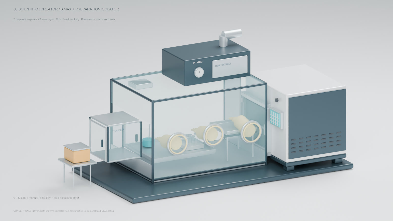
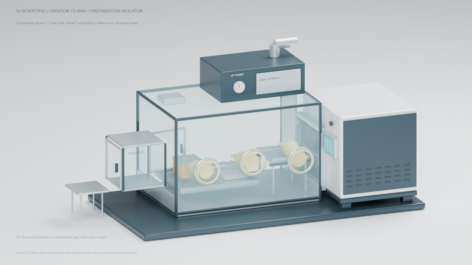
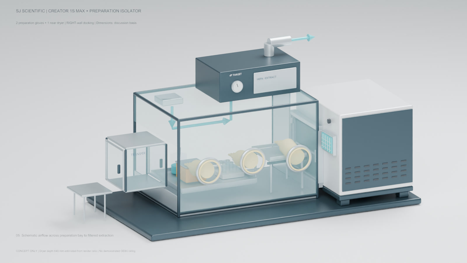
The design question was not simply how to put a glove box around a small lyophilizer. The workspace also had to support liquid preparation and manual vial filling, preserve a practical transfer route, and allow lateral access to a Creator 1S Max without crowding all gloves around the chamber door. Rev. G therefore places the isolator on the operator's left and the lyophilizer on the right, with the glove plane perpendicular to the dryer-door plane.
A 15-second design visualization showing the enlarged preparation bench, three-glove reach zones, left transfer hatch and perpendicular side interface to the Creator 1S Max. It is not footage of an installed machine or a containment test.
Design views for reach and transfer review
Workspace and equipment basis
| Lyophilizer basis | Creator 1S Max; 0.12 m2 shelf area and 300 x 400 mm product shelf |
|---|---|
| Proposed main enclosure | 1200 x 800 x 800 mm |
| Clear preparation target | 600 x 450 mm |
| Glove-port concept | Three nominal 200 mm ports; centres at 250 / 630 / 1030 mm from the enclosure left wall |
| Glove working roles | Left and centre: two-hand preparation pair; right: access near the lyophilizer interface |
| Transfer hatch concept | 350 mm outer cube; 300 mm usable target; two-door interlock |
| Spill-tray concept | Approximately 650 x 550 mm removable tray; material subject to compatibility review |
| Evidence status | Proposed dimensions and concept animation; not a completed installation or performance result |
Why the preparation bench drives the layout
Mixing liquids and manually filling vials need a stable surface, room for vessels and tools, and enough separation from the loading interface to avoid turning every task into a reach around the dryer door. The 600 x 450 mm clear-area target is therefore a workspace requirement, not unused cabinet volume.
The proposed removable spill tray extends beyond that clear target to help manage liquid handling. Its final material, edge detail, cleaning method and removal path depend on product and cleaning-chemistry compatibility.
Three gloves create two different work zones
The left and centre ports are the two-hand preparation pair. Their slight height offset and spacing are intended to cover the bench and transfer-hatch side without clustering the operator around one point.
Only the right glove is positioned near the lyophilizer. That placement supports access review, but one nearby glove does not prove that carrier transfer, door latching or every loading step can be completed one-handed. Representative reach trials are still required.
Side loading needs a supported transfer method
The Creator chamber door faces left into the isolator right wall, while the operator glove plane remains at 90 degrees to the chamber-door plane. The right-side HMI and control bay stay outside the enclosure.
A fixed cooled shelf is the equipment basis. A removable vial carrier or support may bridge preparation and loading, but it must not be described as a pull-out cooled shelf. Carrier stiffness, alignment, cleanability and the door sweep need physical confirmation.
A practical R&D workflow
A proposed sequence is: inspect and establish the enclosure condition; transfer materials through the interlocked hatch; mix and manually fill on the spill tray; move a supported carrier laterally into the chamber; freeze dry; unload and close containers under the intended enclosure condition; then transfer items out and clean the workspace.
Liquid mixing and manual vial filling are optional intended tasks, not an automatic dosing line. Vessel size, fill method, batch count and operator technique must be defined before the layout can be accepted.
Inputs required before a reach trial
Provide representative operators, glove and sleeve details, vessel and vial sizes, carrier mass, loading tools, stopper condition, door opening envelope and the sequence for every item entering or leaving the chamber.
The interface bottom height, seal geometry and net opening are not released in the concept. These details must be resolved before a mock-up or factory reach review can answer whether the arrangement is workable.
Creator preparation-isolator design FAQ
Why are two gloves kept away from the lyophilizer interface?
They form a two-hand preparation pair for liquid mixing and manual vial filling. The third glove supports access near the side-loading interface.
Does the right-side glove prove one-handed lyophilizer loading?
No. Carrier support, alignment, door operation and reach must be tried with representative operators and components.
Is the cooled shelf designed to pull into the isolator?
No. The basis is a fixed cooled shelf. A separate removable vial carrier or loading support may be evaluated.
Does this concept establish an OEB rating or aseptic performance?
No. It is a layout concept. Product hazards, leakage, airflow, filter integrity, cleaning and representative containment testing must be defined separately; aseptic product protection is a separate requirement.